Our Product
Wavegrasp
Distributed passive detection and coarse localization of low-altitude UAVs.
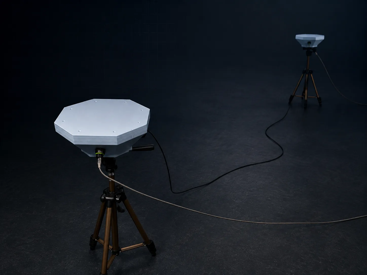
Wavegrasp uses networked acoustic sensing nodes to detect and localize low-altitude drones without relying on the target's control, video, or telemetry links. The current prototype performs acoustic sensing and edge processing, with an architecture designed to accept additional sensing modalities.
Why passive
Most detection today still assumes the target is talking. Ours doesn't have to.
RF-based detection is highly effective when a drone is transmitting through a control link, video downlink, or telemetry channel. Those emissions are structured, informative, and often straightforward to classify. Where they exist, they are a sensible thing to key on.
They are not guaranteed to be present. An aircraft flying a pre-programmed route needs no active control link, and a fibre-guided system carries its command traffic down a spool of glass rather than over the air. Passive acoustics is not a replacement for RF detection — it is independent of it. During powered flight, rotor and propulsion noise remains observable even where usable RF emissions are absent, subject to range, background noise, and the acoustic environment.
RF-link detection
Relies on detectable emissions from the aircraft or its communication link. Autonomous and non-RF-controlled systems may provide no usable RF signal.
✕ no usable signal when the emission is absent
Passive acoustic
Relies on acoustic emissions produced by the aircraft during powered flight. No cooperation or transmission from the target is required.
✓ sensing channel remains available when RF is absent
Current acoustic array implementation
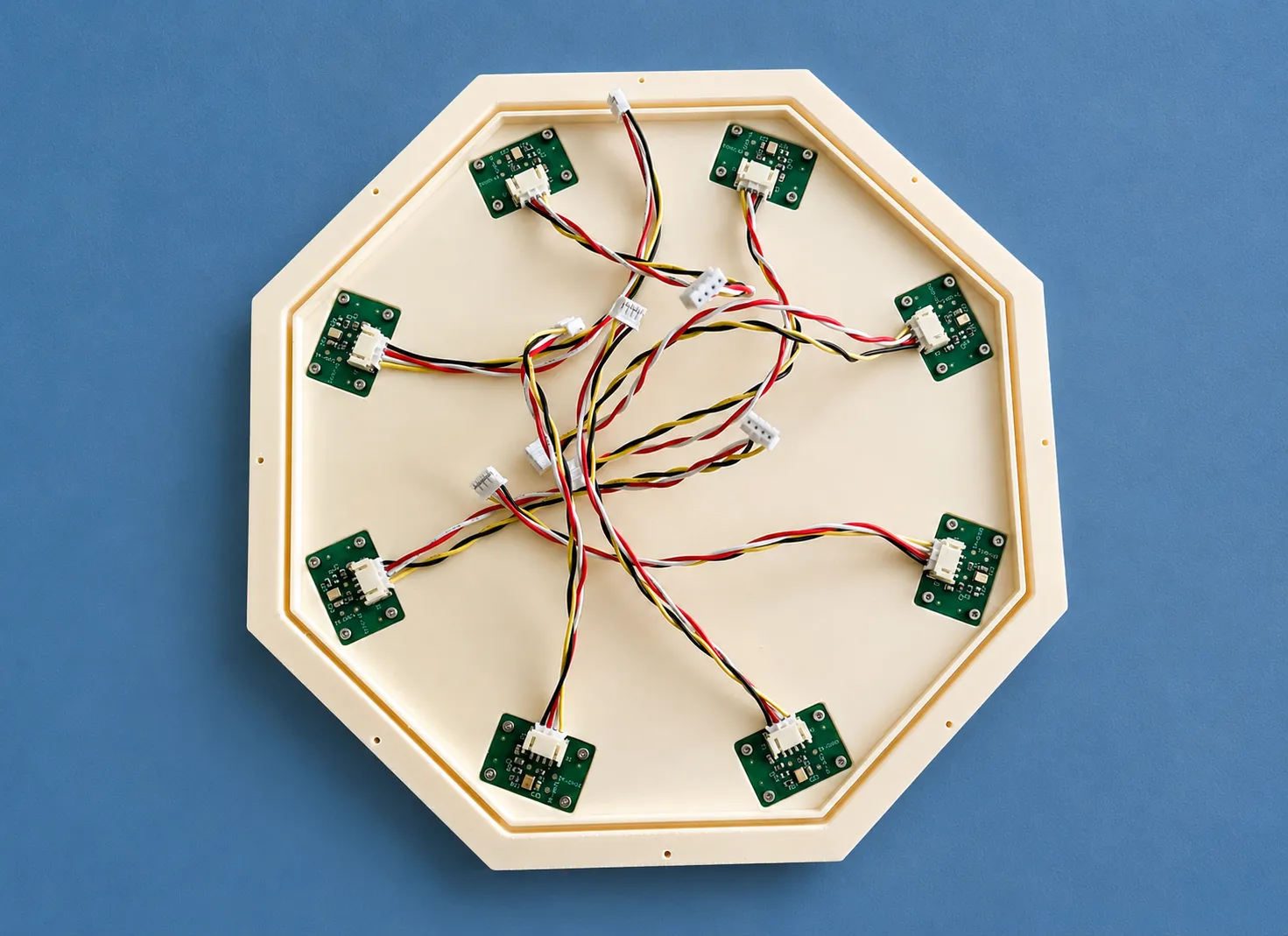
The current prototype uses eight microphones distributed around a 210 mm pitch circle, giving near-uniform azimuthal geometry for direction-of-arrival estimation.
The node architecture is not tied to this geometry. Array spacing and mechanical configuration can be adapted to deployment requirements, and the platform leaves room for additional sensing modalities within the same distributed architecture.
Direction estimates are produced locally at the node and passed into the distributed localization system.
Built in-house
From acoustic front end to enclosure — designed, integrated, and validated in-house.
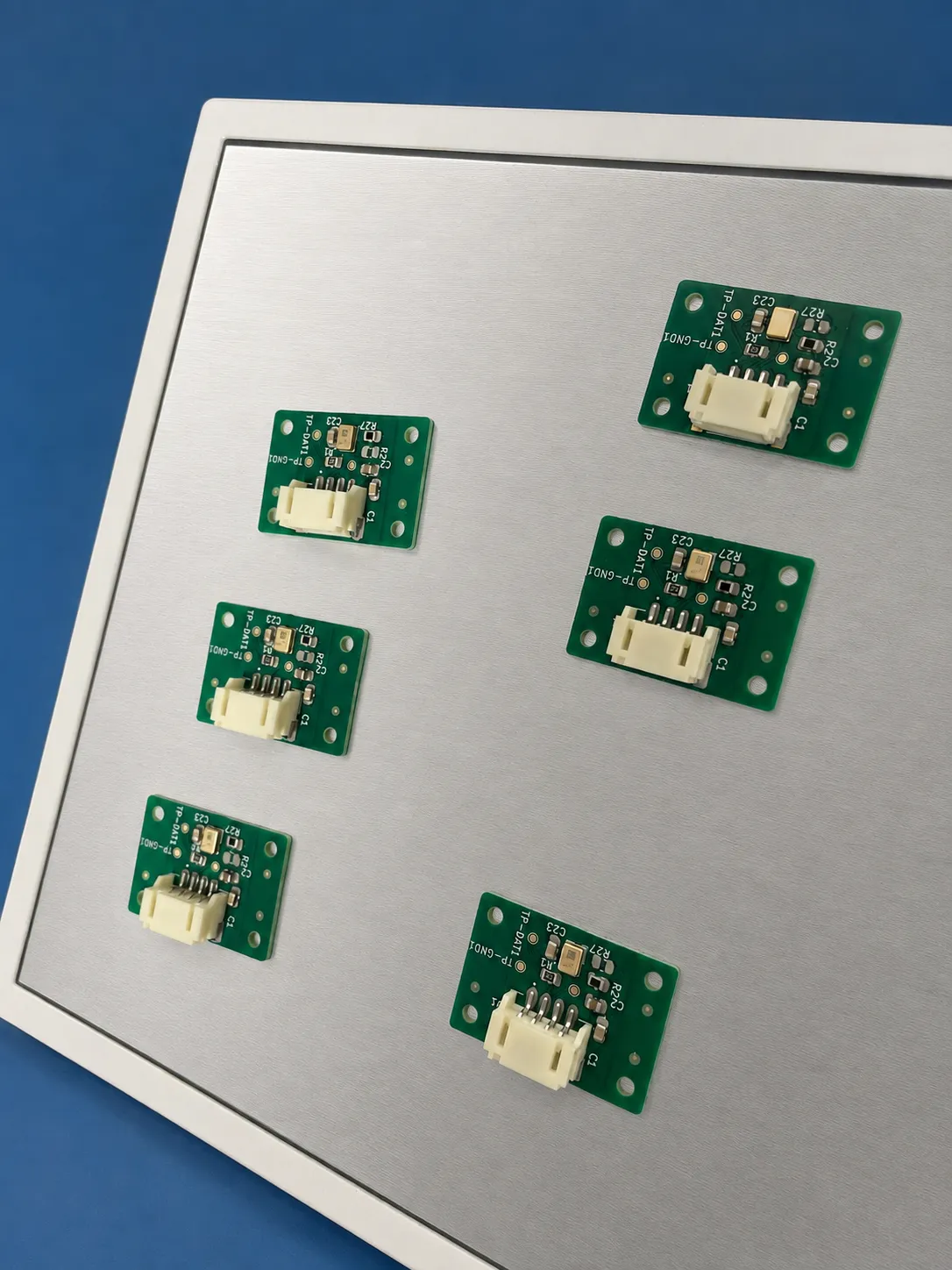
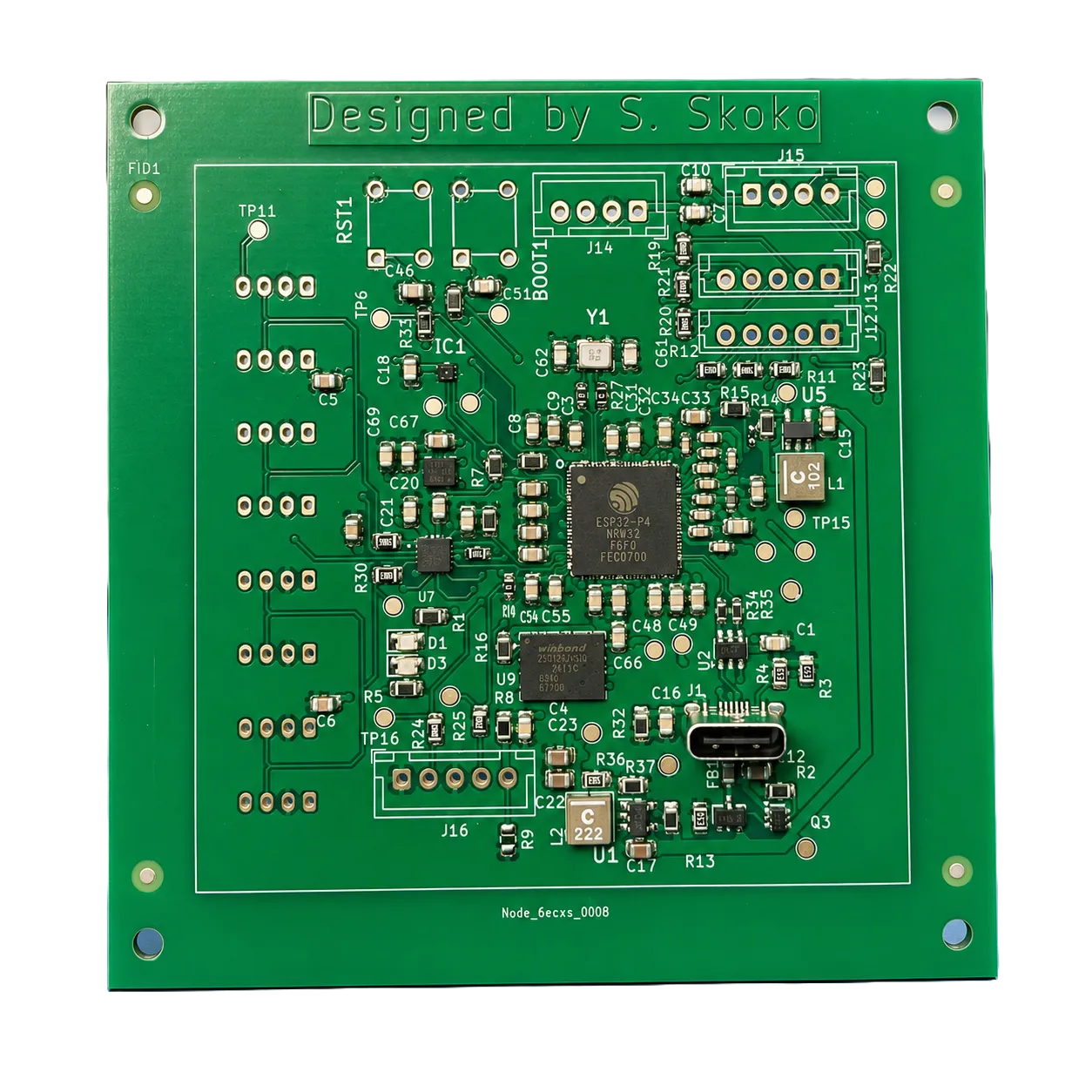
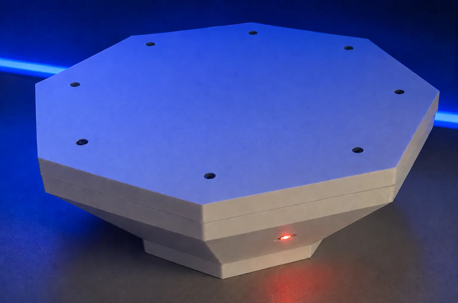
The mechanical platform was developed around the acoustic array, while the acquisition and processing electronics were designed specifically for synchronized multi-channel sensing. The complete signal path is integrated as part of the node rather than assembled from general-purpose acquisition modules.
Custom electronics
Purpose-built acquisition and processing hardware.
8-channel synchronized array
Synchronized microphone channels for directional acoustic processing.
Edge processing
Direction estimation performed locally at the node.
Modular mechanical platform
Mechanical architecture designed to support array iteration and additional sensing components.
From bearing to location
One node estimates direction. Two synchronized nodes resolve a position.
Two nodes Demonstrated
Each node estimates the direction of the same source independently. Two bearings taken from separated positions cross at one point — a bearing is a line, and it takes a second observation to turn it into a place.
Five nodes Target configuration
The planned configuration for the deployed product. Further synchronized nodes contribute additional observations of the same source, improving geometric coverage, redundancy, and the conditioning of the solution. The localization principle is unchanged.
Two-node prototype — measured against surveyed ground truth
A two-node array fixed the position of a source at a known, tape-measured location to sub-2° azimuth and single-digit-percent range accuracy. Seven trials, 2.4 m node separation, controlled conditions. This is the demonstrated result — not a field or operational-range figure.
One array anywhere along a bearing produces the same measurement, so position exists only once a second array, standing elsewhere, contributes its own observation. Going from one node to two is where the distributed problem has to be solved. Beyond two it is replication — the same node, the same interface, the same solver.
A shared time base across separated nodes — designed and built in-house
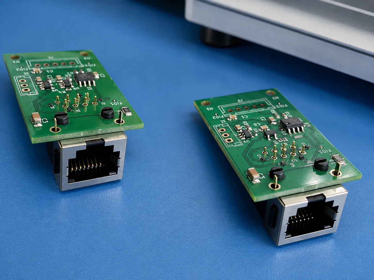
Two bearings only cross at the right point if they describe the same source at the same moment, and that guarantee has to come from hardware. It is the part of a distributed sensing system that is invisible in a diagram and decides whether the diagram is true.
These boards were designed in-house to solve it. They carry the acquisition clock and the data link between nodes as LVDS over ordinary RJ45 cabling — a differential wired connection that holds timing across 15–20 m between separately powered nodes.
The clock travels on the cable, so the network needs neither a radio nor GNSS to stay coherent. Distributed systems that synchronize over the air, or off satellite time, inherit whatever is happening to those signals — jamming, spoofing, or simply no sky view. This one keeps its own time on its own wiring.
The current two-node implementation uses this architecture directly. Additional nodes extend the same interface rather than requiring a different sensing principle. The board is being iterated.
Measured performance
Direction estimation validated against controlled ground truth and an RTK-GPS-tracked drone.
The current prototype has been evaluated in two independent tests: 197 controlled directional measurements, and an outdoor drone fly-by referenced against RTK-GPS.
Both were performed at close range. They validate directional estimation on real hardware — not detection range. Longer-range performance and robustness under varied field conditions are what the next field campaign is for.
- 1.44°Mean absolute bearing error197 controlled measurements · median 0.3°A source at four surveyed cardinal bearings, measured repeatedly. Establishes the estimator's accuracy and spread against a known angle.
- 2.3°Median bearing errorRTK-GPS-tracked outdoor fly-by · close rangeA moving aircraft outdoors, referenced against its own RTK-GPS log. Establishes that the estimator tracks a real target through a changing bearing.
This validates directional estimation at close range. It does not establish maximum detection range.
How this was measured
Slant range during the fly-by was 3.2–6.2 m at 3.1 m altitude — a close-range geometry test of bearing tracking, not a detection-range result. Conditions were 20 km/h wind gusting to 46 km/h. 51 estimation windows over 26 s of overlapping GPS coverage; 44 of 51 within 10°. Range characterization is scheduled for the next field campaign.
Two constants were solved once against the GPS log and held fixed across all windows: the array's rotation relative to compass north (+160°, supplied by an on-board digital compass in the deployed configuration) and a −4 s offset correcting a constant lag between the audio and flight-log time bases. Bearing accuracy reported here is therefore accuracy of relative bearing tracking; absolute compass accuracy depends on the node's own heading reference.
Seven further estimation windows fall after the end of GPS coverage and are excluded rather than scored against extrapolated truth.
System architecture
A modular sensing architecture built around synchronized acquisition, local processing, and distributed operation.
Acoustic front end
Synchronized multi-channel MEMS capture provides the input for directional processing. Array geometry is adaptable to deployment and integration requirements.
Edge processing
Signal conditioning, detection, confidence estimation, and direction-of-arrival processing are performed locally at each node.
Distributed link
A shared time reference and wired node-to-node data interface allow physically separated nodes to contribute measurements to the same localization system.
Environmental context
Motion and vibration sensing identifies mechanically disturbed measurement intervals for quality weighting. Temperature and humidity sensing supports environmental compensation of acoustic measurements.
Sensor expansion
The node architecture supports additional sensing modalities, including optical and ranging sensors, while retaining passive acoustics as the primary wide-area cueing layer.
Current prototype specification
Revision 2 as built and tested. These are the parts fitted to the current hardware, not constraints of the architecture above — a later revision may change any of them.
- Acoustic 8 × digital MEMS microphones (Infineon IM72D128) on a 210 mm pitch circle, single shared clock, sample-level synchronized capture
- Processing ESP32-P4 class edge controller; TDOA / direction-of-arrival estimation; spectral and detection processing on-device
- Inter-node In-house clock and data distribution boards — LVDS over RJ45, validated across a 15 m wired link with zero data errors
- Environmental 6-axis IMU for motion and vibration; temperature and humidity sensing for speed-of-sound compensation
Development status
- Custom sensing hardware — three custom PCB designs developed, assembled, and brought up in-house: acquisition board, microphone carriers, and clock/data distribution
- Single-node direction estimation — validated against controlled ground truth and an RTK-GPS-tracked drone
- Synchronized multi-node operation — two spatially separated nodes over a 15 m wired clock and data link, with no observed data errors during the validated test
- Distributed localization — proof-of-principle position estimation demonstrated against measured ground truth
- Outdoor field campaign — characterize performance across distance, target types, wind, and background-noise conditions
- Detection-range characterization — establish repeatable range envelopes under defined acoustic environments
- Multi-node scaling — extend the validated synchronization architecture toward the target network configuration
- Next-generation node — mechanical refinement and additional sensing capability
Designed for contested and complex environments
Low-altitude UAV awareness
A complementary sensing layer for targets difficult to characterize through control-link emissions alone.
Perimeter monitoring
Distributed passive sensing around facilities and infrastructure.
Sensor fusion
Acoustic bearing information as an input to camera, ranging, or other sensing systems.
Who builds it
Every part of it (schematic, PCB layout, firmware and signal processing) was designed and built in-house, not bought in or outsourced. The physics and mathematical modelling underneath come from computational science. The practice is in the boards above: layout, sourcing, assembly, bring-up, and revising a board on what the testing actually showed, down to 0.35 mm pitch.
More on who builds this →Evaluating passive sensing for a system or deployment?
We are currently developing and validating the platform with partners interested in acoustic detection, distributed localization, and sensor integration.
Discuss technical requirements →