Hardware / 3D CAD Design
3D CAD Design
Parametric 3D modelling for physical products — enclosures, mechanical parts, and the geometry that decides whether a device measures what it is supposed to. Modelled in FreeCAD, printed here, and fitted against the electronics rather than drawn around them once the board is finished.
What this covers
- Parametric 3D modelling in FreeCAD
- Enclosure and housing design
- Mechanical parts, mounts and fixtures
- Geometry driven by the measurement, not by packaging
- 3D printing and iteration in-house
- Design for moulding and machining
- Fit, tolerance and assembly checks
- STEP and STL files you own
Modelled here, then printed and fitted
Ten models, 297 constrained sketches, three design generations — driven by measurement rather than taste.
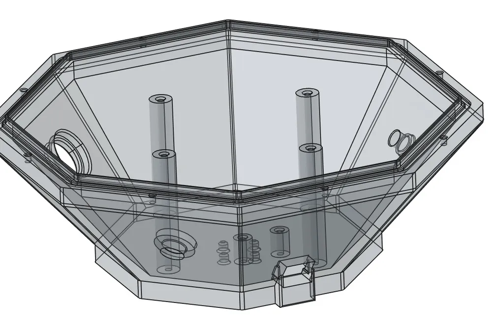
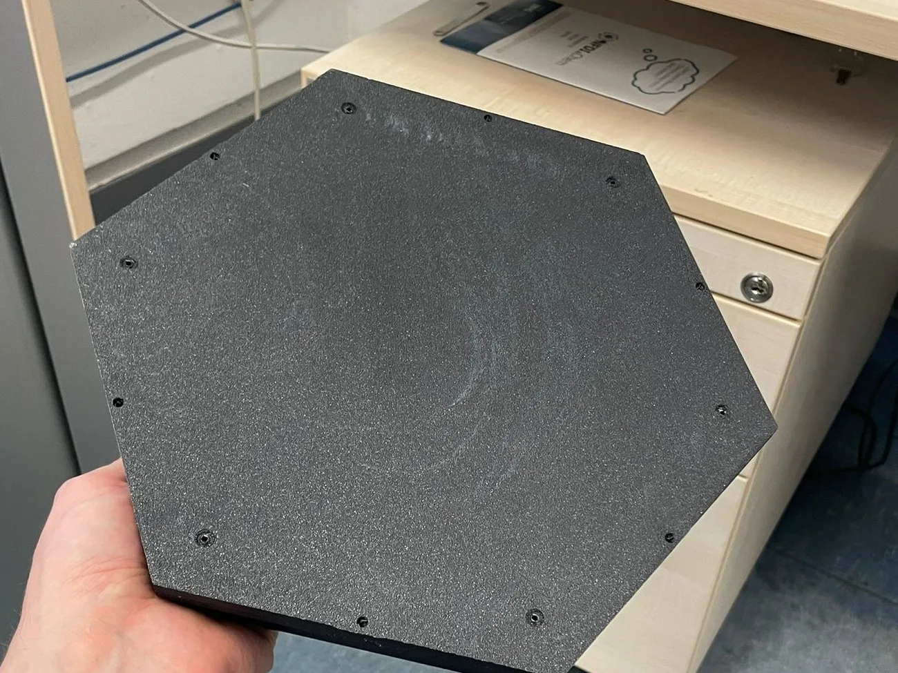
Prototype parts are printed here, which keeps the mechanical iteration loop as short as the electrical one. Where a design later has to move toward moulding or machining it is modelled with that in mind rather than rebuilt from scratch. The practical benefit is that board revisions, enclosure revisions and firmware get iterated against each other in one place, instead of three suppliers waiting on one another.
What good geometry costs
Enclosures modelled as engineering geometry, not as a box drawn around a finished board.
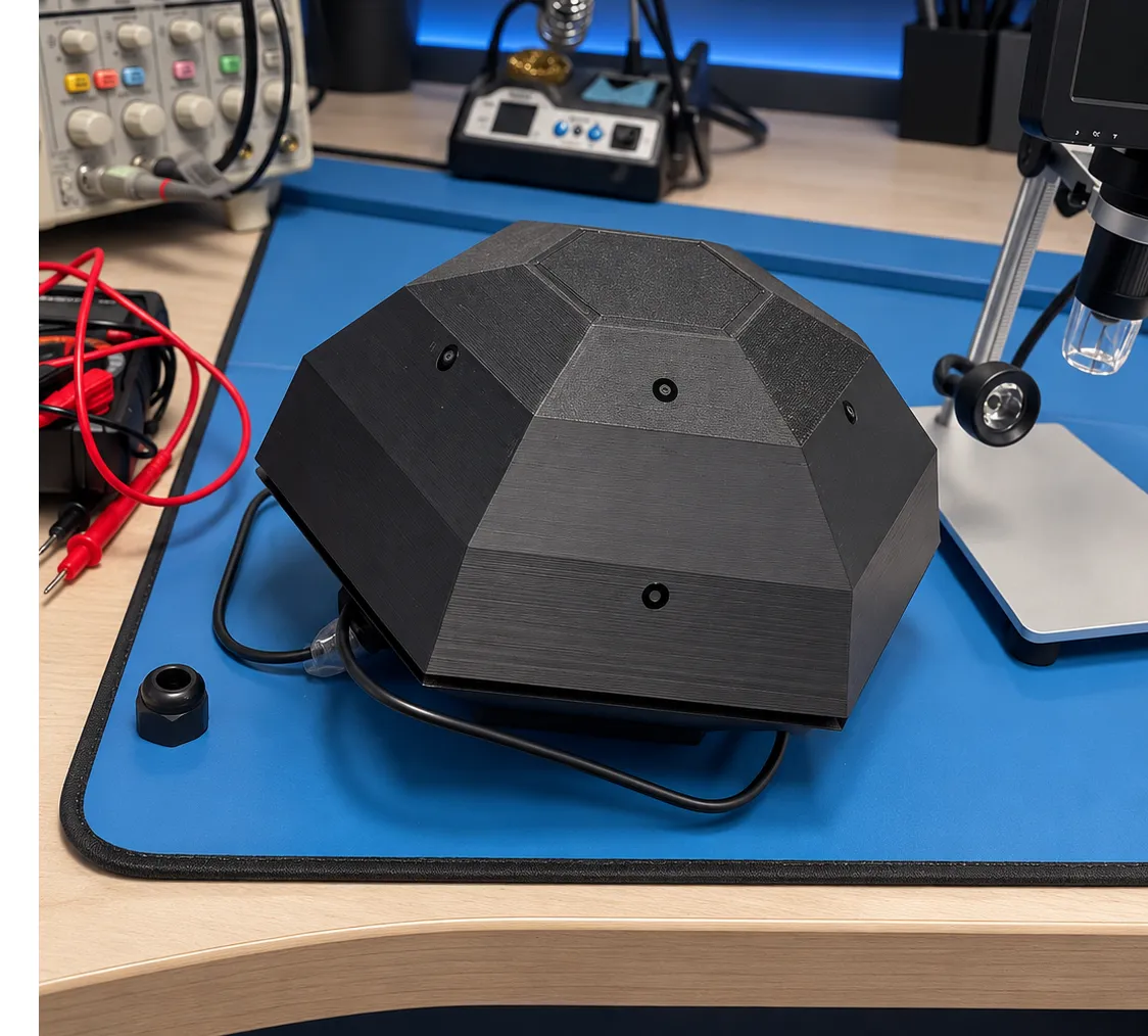
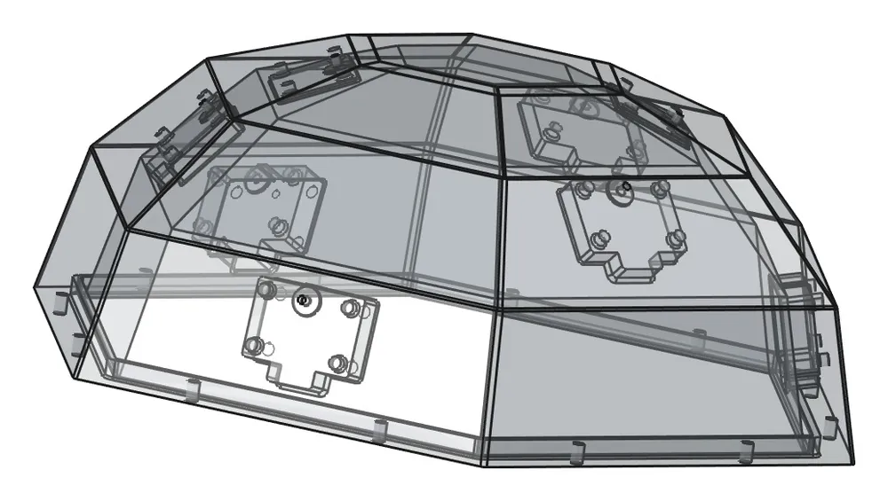
The array that preceded our current one was a faceted dome — eight microphones spread across three tilt bands so the array could resolve elevation as well as bearing. It is a useful illustration of what mechanical design costs when it is done properly.
The tilt came from stacking rings of decreasing radius, so every facet met the vertical at a different angle. Wall thickness follows that angle: near-vertical facets are thick, the steepest are thin. Each microphone needs a recess of a particular depth in front of it, and at the top there was barely any wall left to recess into — so the seat depth had to be re-dimensioned band by band, reaching zero at the highest one. Because sketches are plane-dependent, none of it could be copied; every seat was drawn on its own plane, across roughly fifty-five of them.
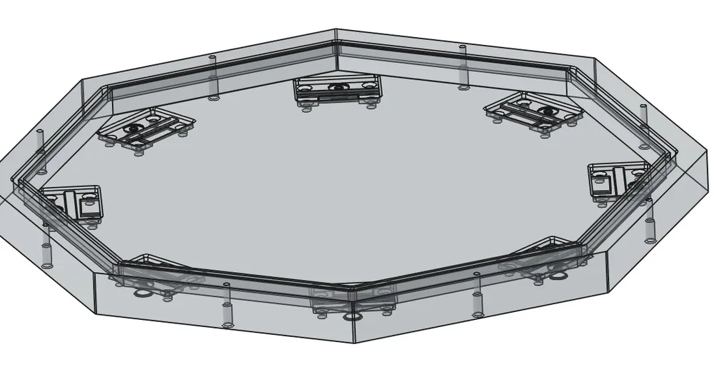
It worked, and it is also why we changed course. With microphones on different planes the acoustic path in front of each one could not be held constant. The flat 210 mm ring that replaced it puts all eight on a single plane at a uniform 3.2 mm depth, and measured bearing resolution improved. The exotic geometry was not wasted — it was characterized, and it lost on the numbers.
That is the argument for doing mechanical work alongside the electronics and the signal processing rather than downstream of them. The geometry here was never a packaging decision; it was an acoustics decision that happened to be expressed in plastic.
What the work usually involves
Parametric modelling
Models built from constrained sketches and driven by dimensions, so a change to one number propagates instead of requiring the part to be redrawn.
Geometry that carries the measurement
Where a sensor sits, what it sees, and what the material in front of it does to the reading. On a sensing product this is the design, not the packaging.
Fit and tolerance
Clearances, press fits, fastener access and the half millimetre that decides whether the connector reaches the panel. Checked against the board, not guessed.
Printing and iteration
Parts printed here, so a fit problem found on Monday is a revised part on Tuesday. The mechanical loop runs as fast as the electrical one.
Toward production
Draft, wall thickness and parting lines considered while it is still cheap, so a design that later needs moulding or machining is adapted rather than rebuilt.
Files you own
Native models, STEP for whoever manufactures it, STL for printing, and the notes explaining why a dimension is what it is.
Have a part that has to be right?
Bring a sketch, a board the part has to fit around, or a shape that is not working. Electronics are welcome but not required — mechanical work stands on its own here.
Discuss a project →